How To Start the New Margin Scheme Special Database?
Introduction
GST is normally due on the full value of goods sold. The margin scheme allows a GST Margin Scheme registered person (GST MS registered person) who meets all the conditions to calculate and charge GST on the margin i.e. the difference between the price at which the goods were obtained and the selling price. If no margin is made (because the purchase price exceeds the selling price) then no GST is charged and payable.
For the purpose of GST, margin under this scheme means the difference between selling price and purchase price. If there is any value being added to the eligible goods such as cost for repairing, this cost is part of the margin other than profit. In other words, the value added must be included in the selling price and not the purchase price.
Therefore, we have designed a database structure specially for business which has margin scheme involvement. The modules required are:-
- SQL Accounting Basic (GST compliance)
- DIY field
- DIY script
- Project (use to record Car Plate number)
See below the sample process flow:
SETUP MARGIN SCHEME DATABASE
- Get the NEW database structure for Margin Scheme (in backup format) from this link
- REDIRECT [[1]]
- Restore this backup.
- Enter the user ID and password with “ADMIN” to login.
| Sections | Explanation |
|---|---|
| Customer Info from SO | Basically, the customer and others information copy from SO. |
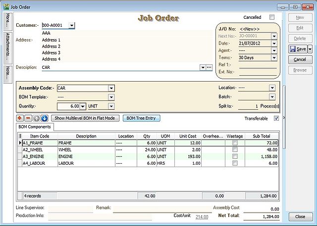
| Assembly Item Info (Header & Footer) | Assembly item transferred from SO. It will determine the BOM Components required and the assembly unit cost. |
| BOM Components Details | Total components quantity requirement to meet the total output. |
JO Transfer From SO
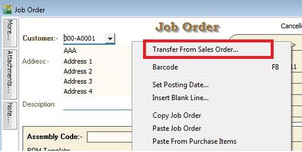
1. RIGHT CLICK on Job Order (Title).
2. CLICK on Transfer From Sales Order in the small menu.
Document Transfer (SO --> JO)
1. Pick the item from SO list.
2. INPUT X/F qty wish to transfer into JO.
3. CLICK OK button to proceed next.
4. After transferred from SO, you will see the BOM components qty updated in Job Order.
BEFORE SAVE - JO Check on the Available Stock Balance
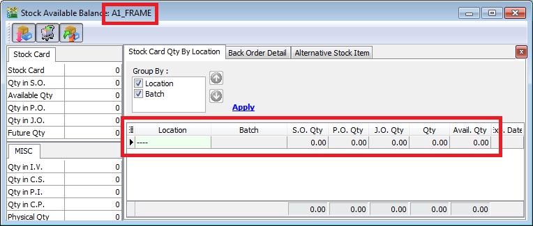
1. HIGHLIGHT on the component items and PRESS on F11 keyboard button (Available Stock Balance).
2. Below is component “FRAME” stock available balance,
Result for component “FRAME” item:
SO Qty = 0.00
PO Qty = 0.00
JO Qty = 0.00
Qty (On Hand) = 0.00
Available Qty = 0.00
NOTE: Qty (On Hand) results above are trying to show the stock movement purpose only.
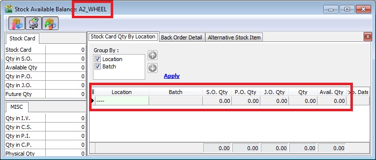
3. Below is component “WHEEL” stock available balance,
Result for component “WHEEL” item:
SO Qty = 0.00
PO Qty = 0.00
JO Qty = 0.00
Qty (On Hand) = 0.00
Available Qty = 0.00
NOTE: Qty (On Hand) results above are trying to show the stock movement purpose only.
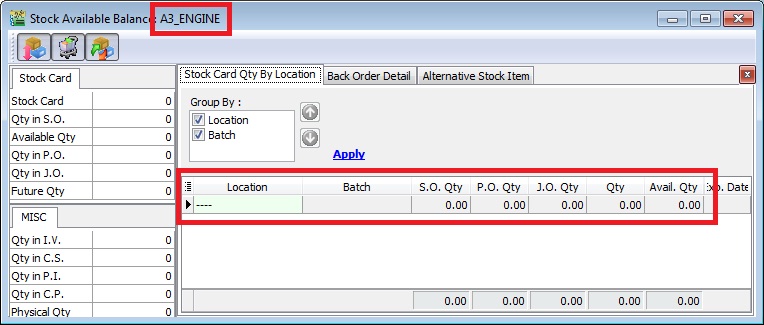
4. Below is component “ENGINE” stock available balance,
Result for component “ENGINE” item:
SO Qty = 0.00
PO Qty = 0.00
JO Qty = 0.00
Qty (On Hand) = 0.00
Available Qty = 0.00
NOTE: Qty (On Hand) results above are trying to show the stock movement purpose only.
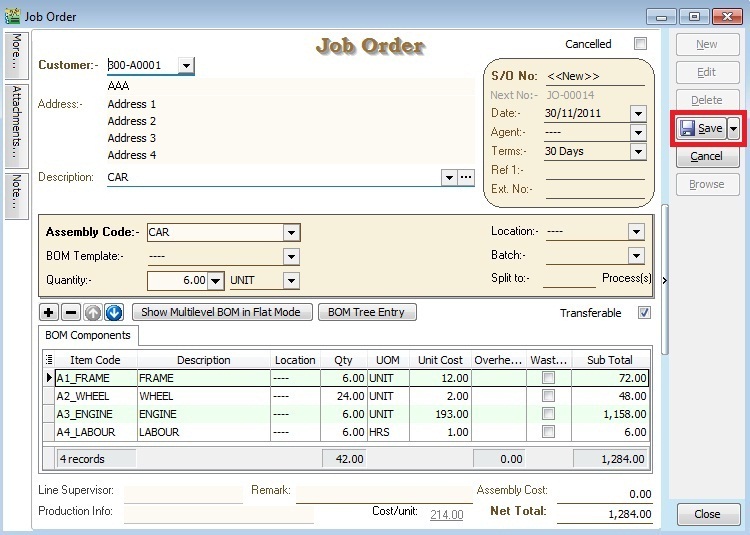
Save Job Order Document
1. CLICK on SAVE button.
AFTER SAVE - JO Check on the Available Stock Balance
1. HIGHLIGHT on the component items and PRESS on F11 keyboard button (Available Stock Balance).
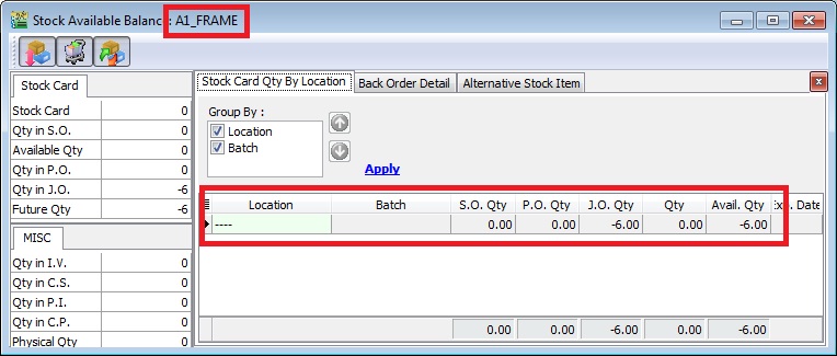
2. Below is component “FRAME” stock available balance,
Result for component “FRAME” item:
SO Qty = 0.00
PO Qty = 0.00
JO Qty = -6.00
Qty (On Hand) = 0.00
Available Qty = -6.00
NOTE: Qty (On Hand) results above are trying to show the stock movement purpose only.
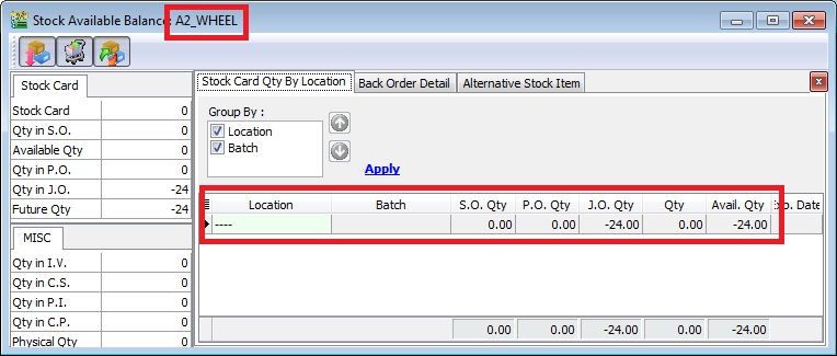
3. Below is component “WHEEL” stock available balance,
Result for component “WHEEL” item:
SO Qty = 0.00
PO Qty = 0.00
JO Qty = -24.00
Qty (On Hand) = 0.00
Available Qty = -24.00
NOTE: Qty (On Hand) results above are trying to show the stock movement purpose only.
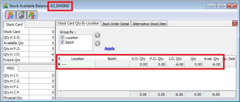
4. Below is component “ENGINE” stock available balance,
Result for component “ENGINE” item:
SO Qty = 0.00
PO Qty = 0.00
JO Qty = -6.00
Qty (On Hand) = 0.00
Available Qty = -6.00
NOTE: Qty (On Hand) results above are trying to show the stock movement purpose only.
Split to X Process
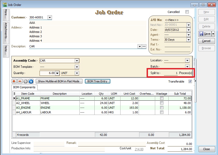
1. With this field, user able to assign number of processes/machines in one Job Order/Stock Item Assembly to produce same End Products using same range of BOM components.
2. For example, To make a cup of MILO KAO KAO, it needs - MILO Powder x 5 spoons - Sugar x 0.5 spoon - Water x 100ml
In order to make 100 cups of milo from one Job Order created, we need 10 persons to make it more efficient. Therefore, we have to input "Split to 10 process(s)", it means 10 persons processing. Job Order will be break the BOM components into 10 processes like below:
| No of process(s) | 1 | 2 | 3 | 4 | 5 | 6 | 7 | 8 | 9 | 10 | TOTAL |
|---|---|---|---|---|---|---|---|---|---|---|---|
| MILO Powder | 50 | 50 | 50 | 50 | 50 | 50 | 50 | 50 | 50 | 50 | 500 spoons |
| Sugar | 5 | 5 | 5 | 5 | 5 | 5 | 5 | 5 | 5 | 5 | 50 spoons |
| Water | 1000 | 1000 | 1000 | 1000 | 1000 | 1000 | 1000 | 1000 | 1000 | 1000 | 10000 ml |
NOTE: Preview and select the standard report name "Job Order 2 with Multipler - 30 Columns (without cost)".
Show Multilevel BOM in Flat Mode
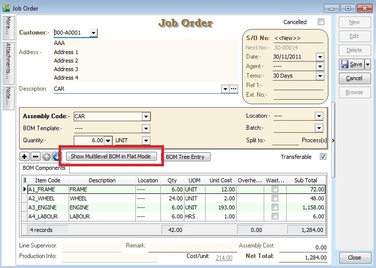
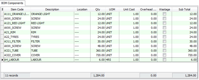
1. This function ables to drill down to the flatten or deepest level of the BOM structure. For example, the CAR multilevel BOM structure.
| Level 0 | Level 1 | Level 2 | Level 3 |
|---|---|---|---|
| Car | Frame | Front Frame | Orange |
| Car | Frame | Front Frame | Screw |
| Car | Frame | Back Frame | Red Light |
| Car | Frame | Back Frame | Screw |
| Car | Wheel | Rim | |
| Car | Wheel | Tyres | |
| Car | Engine | Engine Block | Filter |
| Car | Engine | Engine Block | Screw |
| Car | Engine | Piston | Tube |
| Car | Engine | Piston | Cover |
| Car | Labour |
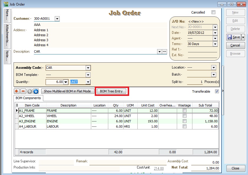
2. Before FLAT mode, the BOM components shown at LEVEL 1.
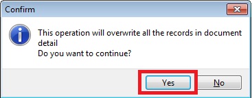
3. CLICK on Show Multilevel BOM in Flat Mode button. It will prompted a message. See below screenshot.
- PRESS NO to remain the BOM components at LEVEL 1.
- PRESS YES to flatten the multilevel BOM till LEVEL 3.
4. After FLAT mode, the BOM components will be shown at LEVEL 3.
BOM Tree Entry
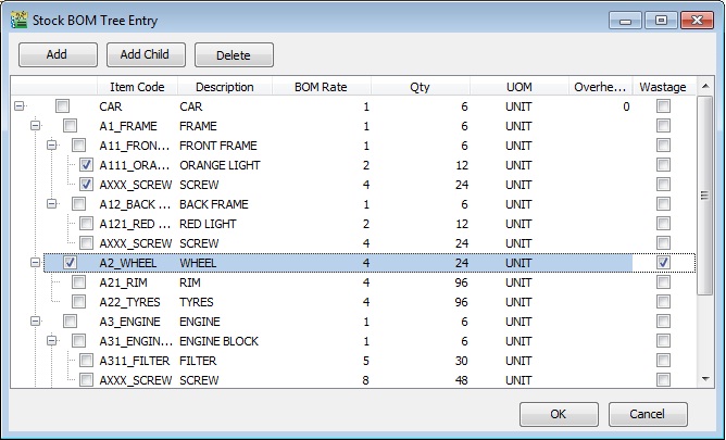
1. Some manufacturing company need to modify and overwrite the standard BOM structure during the entry stage. This button is help to add/remove the components to overwrite the BOM structure.
2. Click the "BOM Tree Entry" button.
3. You can drill down all the BOM structure.
4. Tick the components in the tree you wish to insert into the Job Order/Stock Assembly/Disassembly.
5. Press OK to confirm.
| Button | Function |
|---|---|
| Add | To add new components at LEVEL 1 ONLY |
| Add Child | To add new child components start from LEVEL 2 onwards |
| Delete | To remove the components at all LEVEL 1, 2, 3, 4, ... |
